1Features
- MYIR MYC-YT113 Linux system-on-module on a 140-pin footprint
- Gigabit Ethernet: YT8531SH PHY over RGMII, ESD arrays on all four pairs
- SIM7080G modem for LTE-M, NB-IoT and GNSS, with SMA antenna ports and a SIM holder
- Two RS-232 channels (MAX3232) and one RS-485 channel (THVD1400) with surge protection
- 12 V input behind a PTC fuse, TVS, reverse-polarity MOSFET and common-mode EMI filter
- Two synchronous bucks and a low-noise LDO, every rail behind its own resettable fuse
- Software-controlled modem power key, so a hung modem can be restarted remotely
2Specifications
- Processor
- MYIR MYC-YT113 SoM
- Ethernet
- 10/100/1000 · YT8531SH
- Cellular
- LTE-M / NB-IoT + GNSS
- Field buses
- 2× RS-232 · 1× RS-485
- Input
- 12 V DC
- Rails
- 5 V · 3.8 V · 3.3 V
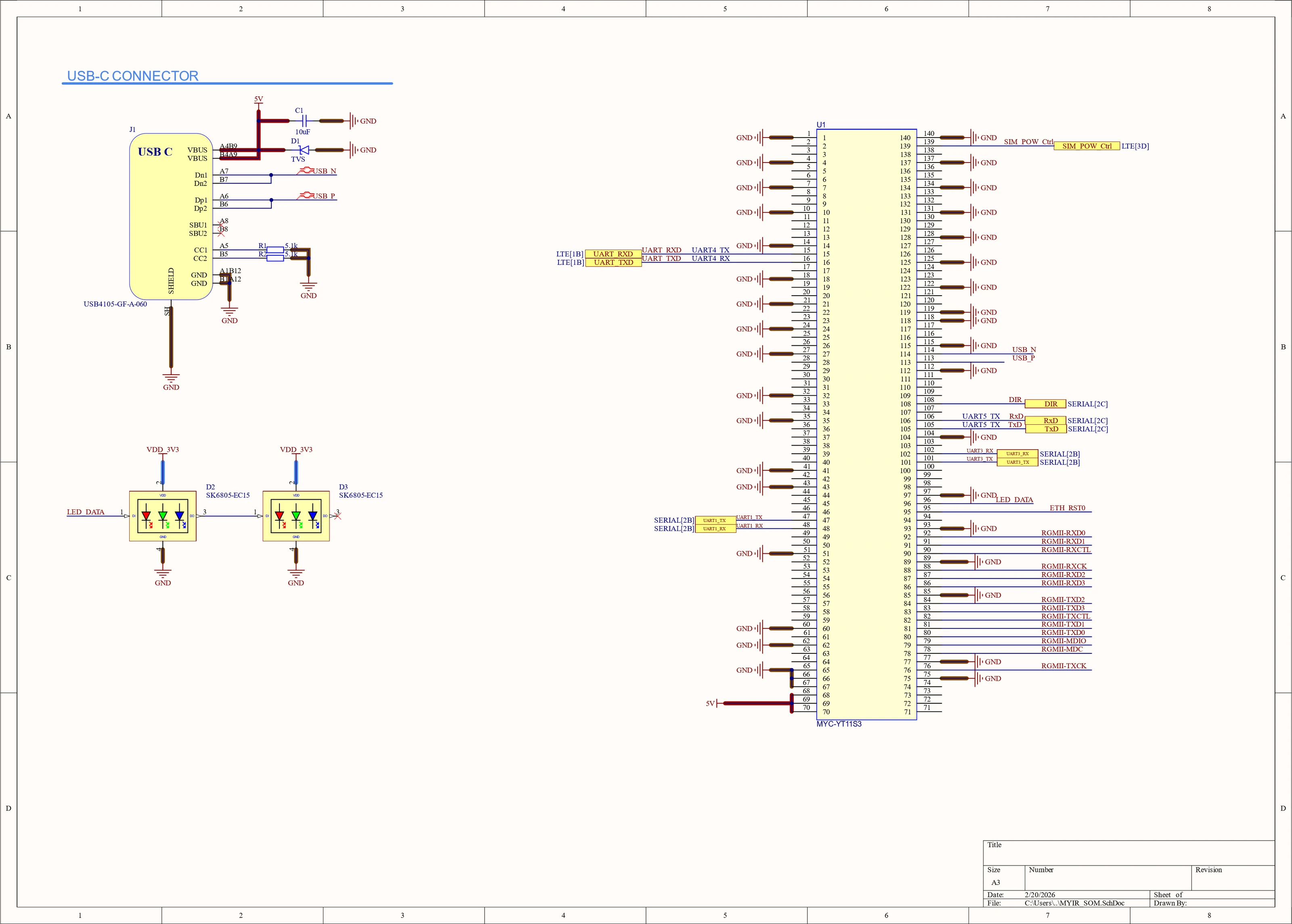
- Schematic
- 5 sheets
- Design tool
- Altium Designer
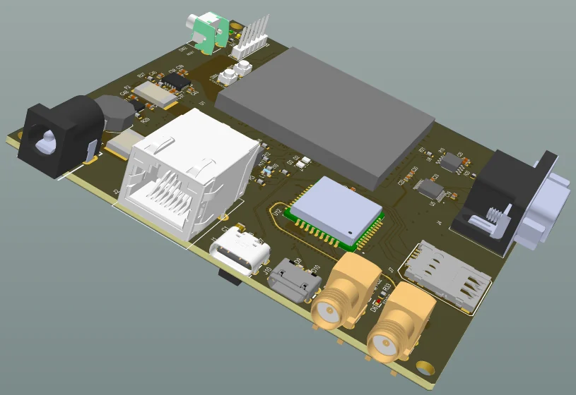
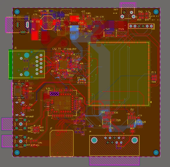
3Figure 1 — Board
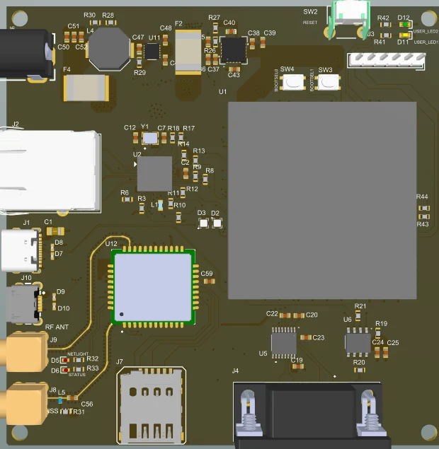
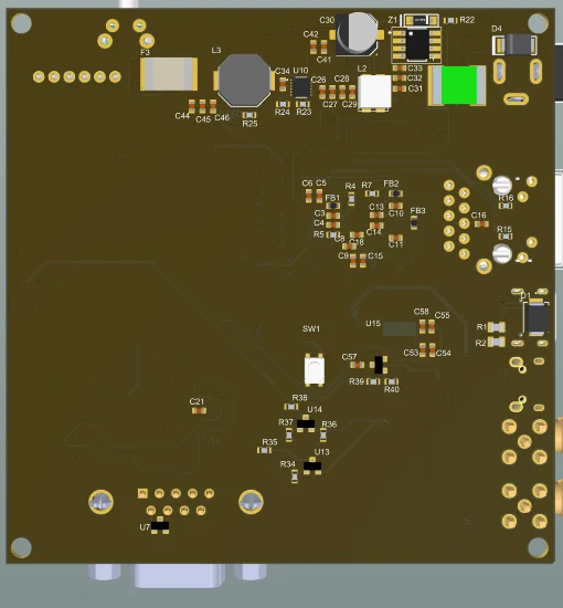
4On the bench
5Description
A gateway for the field side of an installation. It listens on the serial buses industrial equipment still speaks and forwards the data over wired Ethernet or, where there is no cable, over the cellular network. A Linux system-on-module does the work; the carrier board around it is five sheets of interfaces and power.
The SoM's RGMII port drives a YT8531SH gigabit PHY whose mode, address and RX clock delay are set by strap resistors, with ferrite-isolated analog and digital supplies and TVS arrays in front of the magnetics. A SIM7080G modem covers LTE-M and NB-IoT, with GNSS on a second antenna. It runs from its own 3.8 V rail at 1.8 V logic, so its UART is level-shifted with transistors and its power key is driven by the SoM — software can restart a modem that has stopped answering.
Power enters at 12 V through a PTC fuse, a TVS and a P-channel MOSFET that blocks reverse polarity, then a common-mode choke. Two LMR51450 synchronous bucks make 5 V and the modem's 3.8 V, a low-noise NCP59744 LDO derives 3.3 V from the 5 V rail, and each rail leaves through its own resettable fuse, so a short on one connector can't take the rest of the board down with it.
6Schematics