1Features
- ESP32-S3-MINI-1 module with Wi-Fi, Bluetooth LE and 8 MB flash
- USB-C wired straight to the S3's native USB — no USB-to-UART bridge
- LSM6DS3TR-C six-axis IMU on I²C, both interrupt lines on GPIO
- BQ24040 Li-ion charger with a charge-status LED
- Automatic USB / battery power path: Schottky from VBUS, P-MOSFET from the cell
- TLV75801 LDO for the 3.3 V rail
- Reset, boot and user buttons, a user LED and a UART / I/O header
2Specifications
- MCU
- ESP32-S3-MINI-1-N8
- IMU
- LSM6DS3TR-C · 6-axis
- Charger
- BQ24040
- Regulator
- TLV75801 · 3.3 V
- USB
- USB-C, native
- Power
- USB or 1-cell Li-ion
- Design tool
- Altium Designer
3Figure 1 — Board
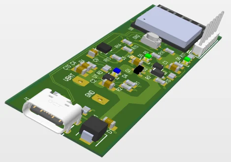
4On the bench
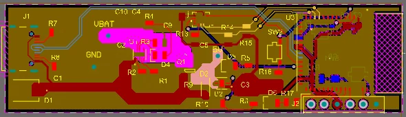
5Description
A small battery-powered sensor node built around the ESP32-S3-MINI-1. The S3's own USB peripheral is wired straight to the USB-C connector, so the same port flashes firmware, opens a serial console and charges the cell — there is no separate USB-to-UART bridge on the board.
Power comes from USB or a single Li-ion cell, and the board changes over without any help from firmware. VBUS feeds the regulator through a Schottky diode; the cell feeds it through a P-channel MOSFET whose gate is held by VBUS, so the battery path turns off the moment USB is plugged in and back on when it is removed. Meanwhile a BQ24040 charges the cell and reports on an LED, and a TLV75801 LDO turns whichever source is present into the 3.3 V rail.
Motion comes from an LSM6DS3TR-C accelerometer and gyroscope on I²C, with both interrupt pins routed to GPIO so the ESP32 can sleep until the sensor has something to report. Reset and boot buttons, a user button and LED, and a header with the UART and two spare signals cover bring-up.